
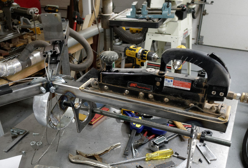
This is the first collaboration with Marcel Braun. He needed a machine to squeeze large pieces of hot glass into triangular shapes. It's being built in a very general, expandable way to accomodate future needs. The graphite forming dies are interchangeable
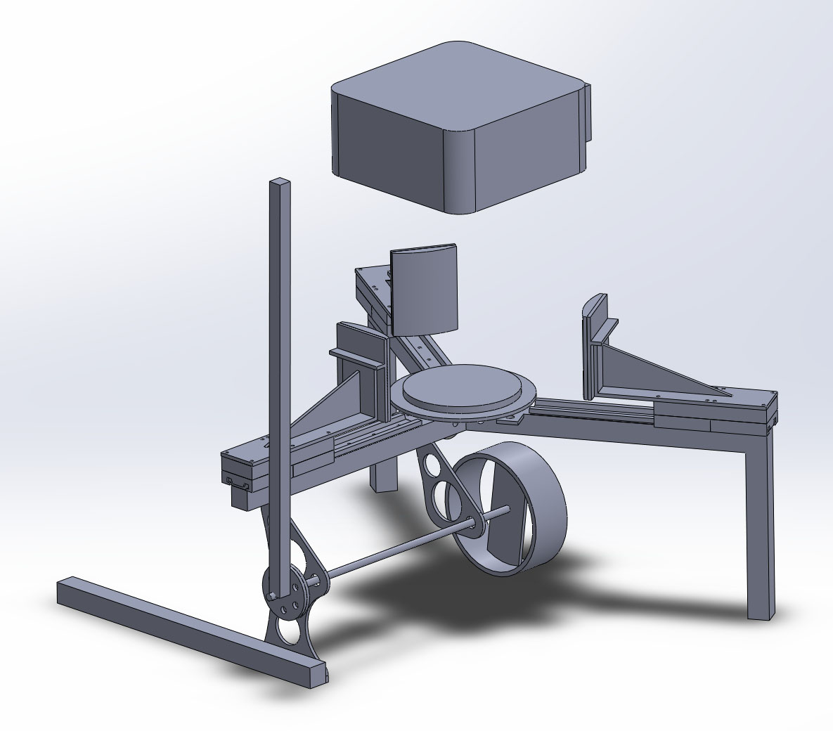
The CAD model
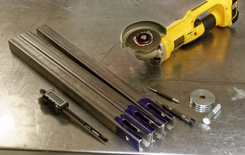
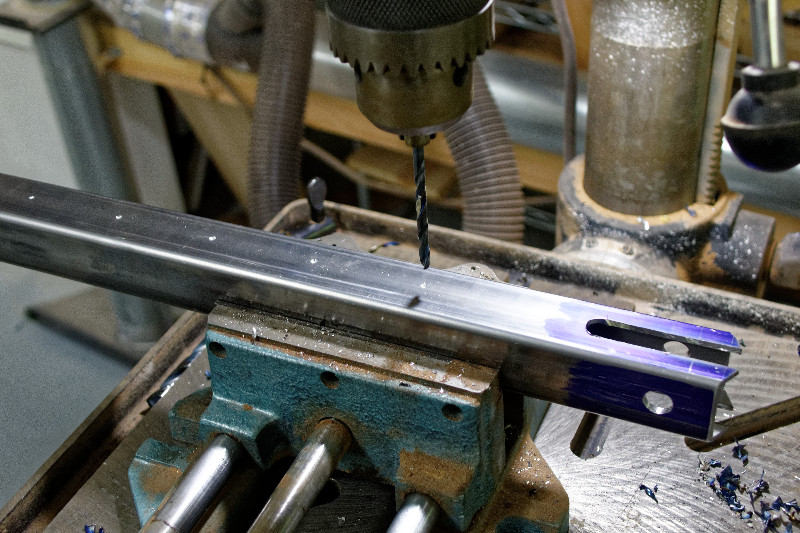
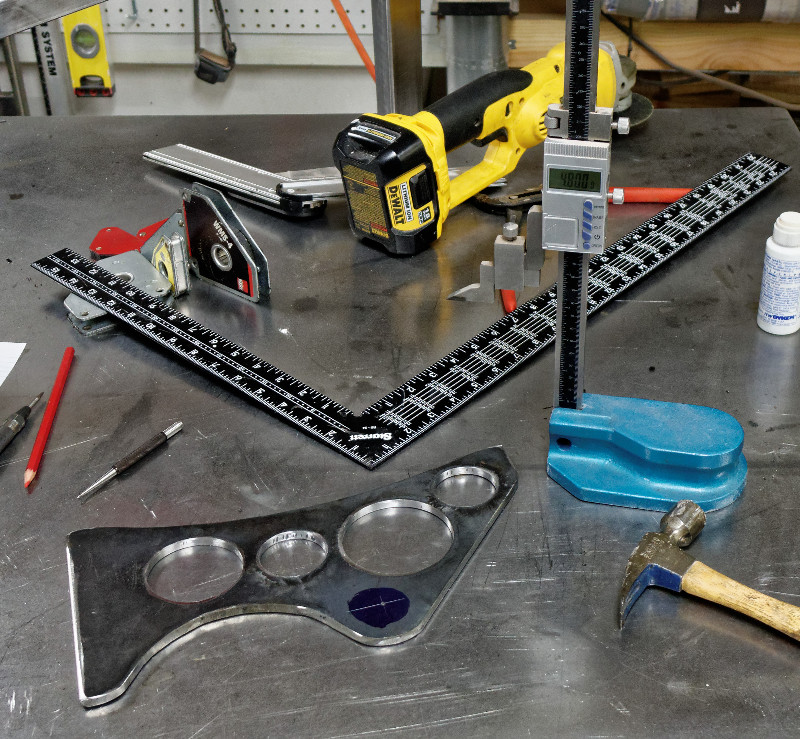
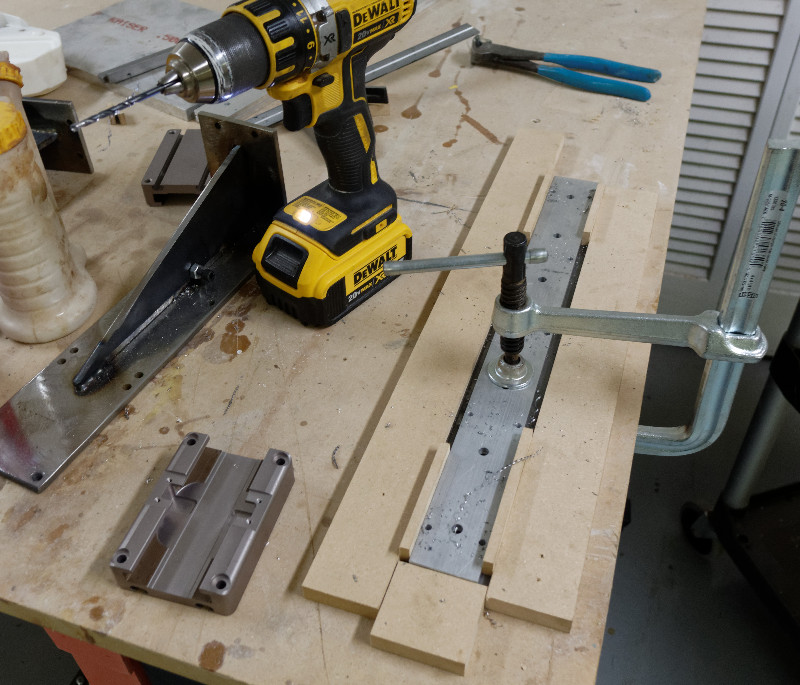
Pieces cut on chop saw. Layout done with digital distance gauge. Center punched and drilled on drillpress. Slots cut with angle grinder
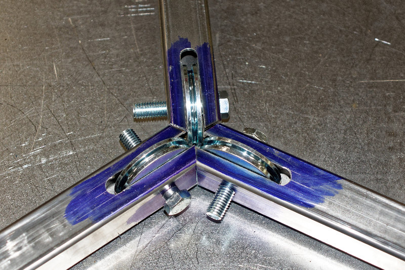
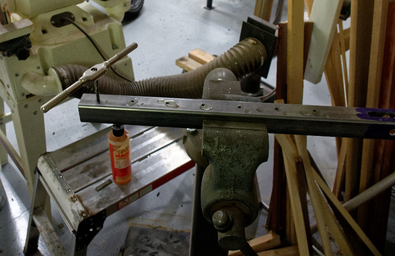
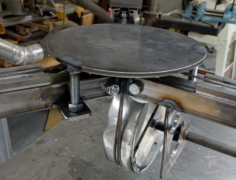
Check fit with cable pulleys
The CNC router can't drill steel, but it can make center marks
Holes drilled on drillpress, following CNC marks
Manually tapped
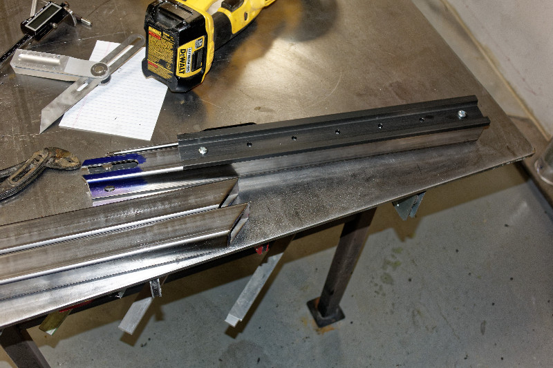
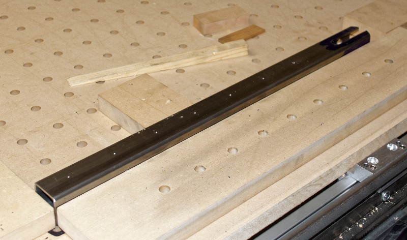
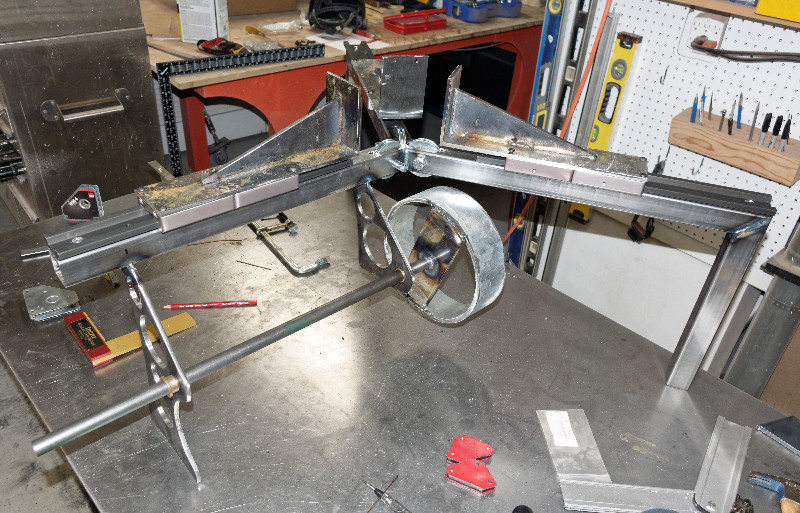
Check fit with slide rail
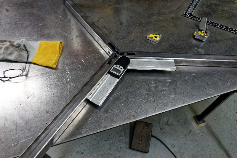
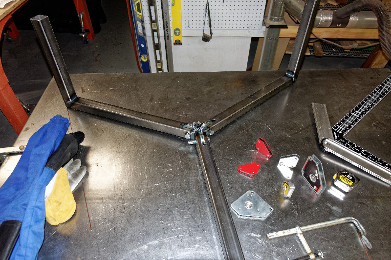
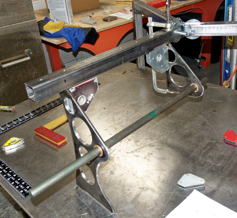
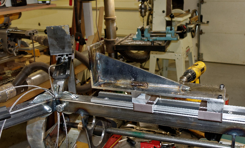
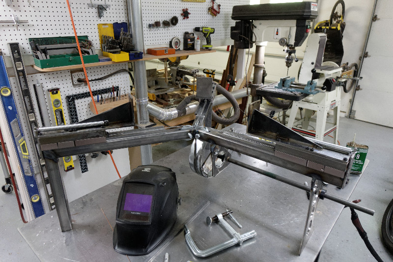
Use digital angle gauge to set up for welding
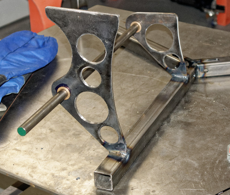
After welding, insert pulleys and check fit
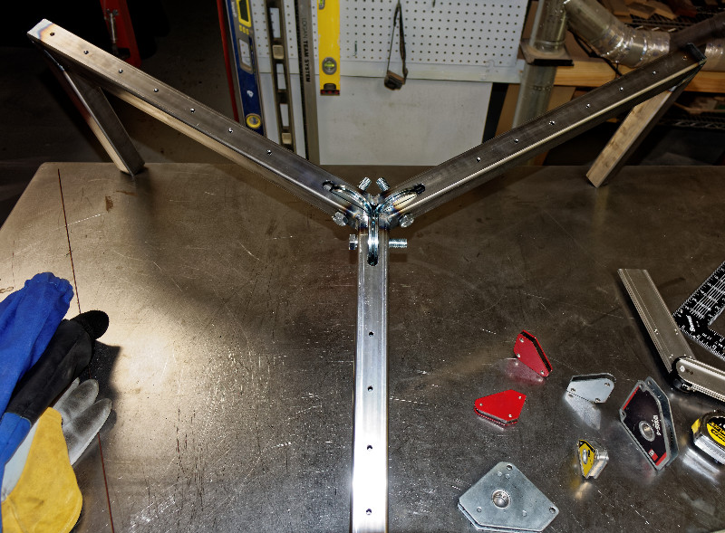
All is good
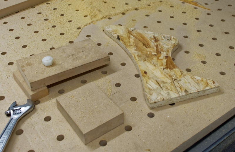
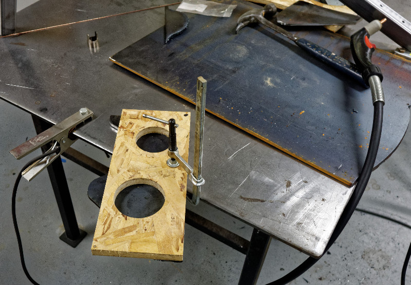
I haven't figured out how to mount the plasma cutter to the CNC router, so this is a workaround. Cut some templates
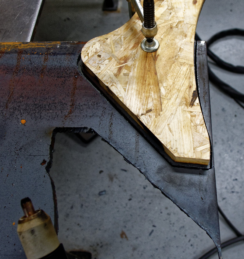
Use the templates to guide the plasma cutter. Crappy cut, maybe I need to change the tip
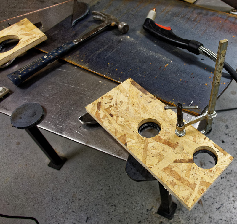
Cutting jig for holes
Much nicer cut quality
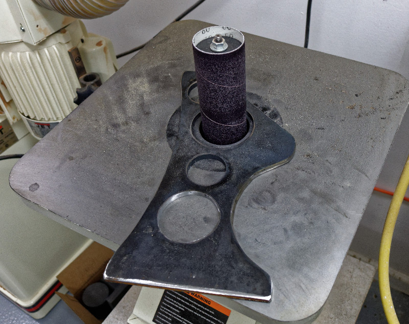
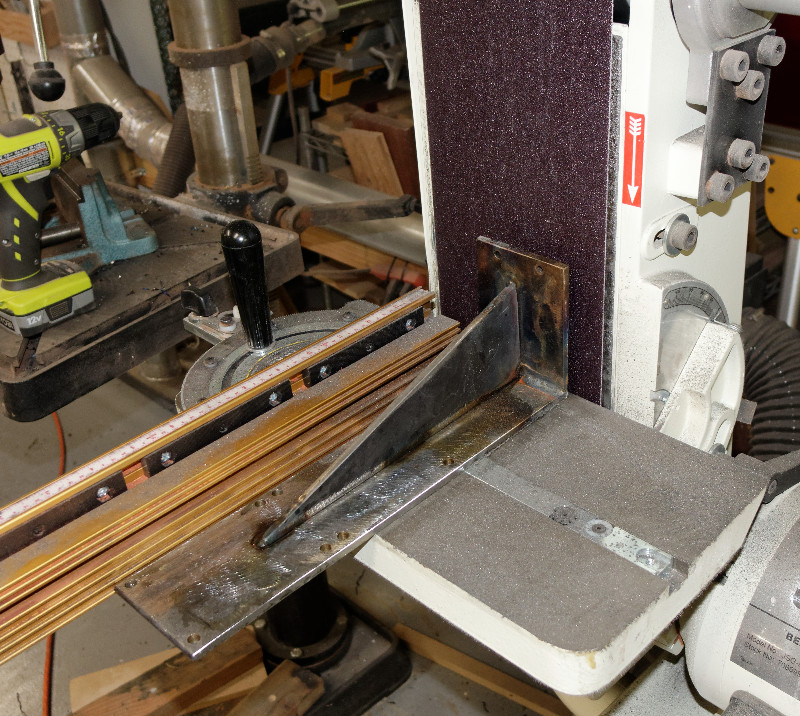
Use sander to finish holes
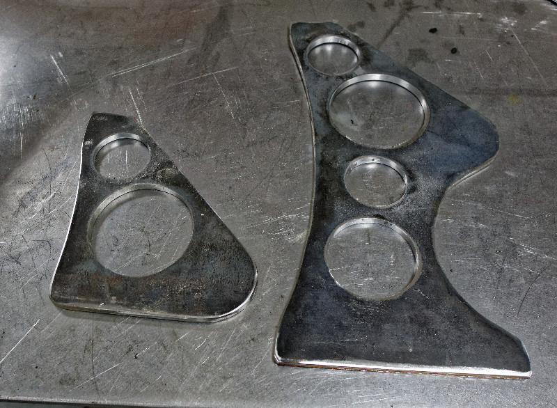
Finished pieces. No, the design wasn't necessary, boring plain shapes would have worked as well. But, I like design
The bearing hole needs to be more precise, so layout with digital height gauge
Clamped and ready for welding
All is well
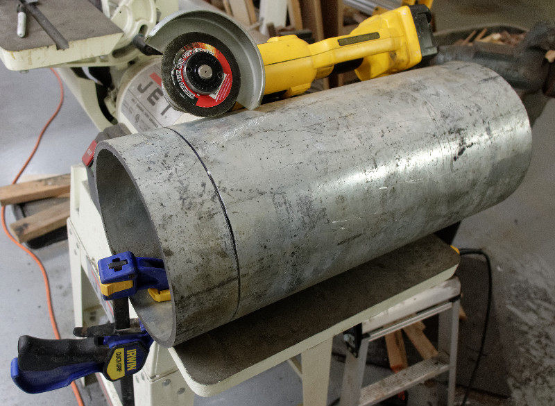
An angle grinder can cut 8" steel pipe..slowly
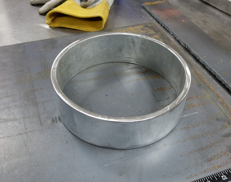
Drum ready for next step
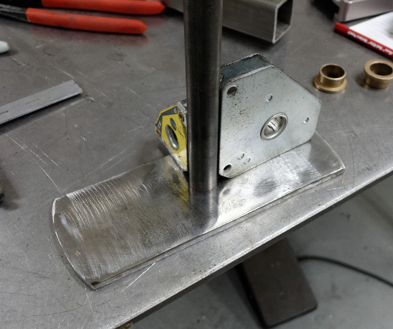
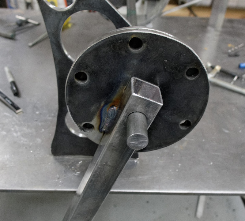
Prepare to weld shaft to drum part
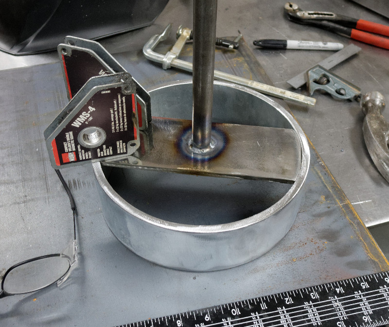
Now weld the parts together
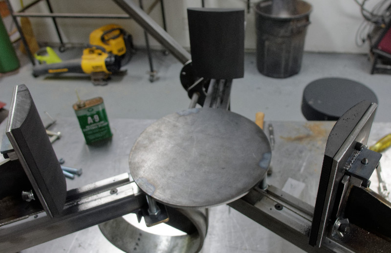
The drum spins fairly concentric and straight for a weldment
Use the CNC router to mark holes
Even when being careful, weldments are never accurate, so fix up the inaccuracies with abrasive machining
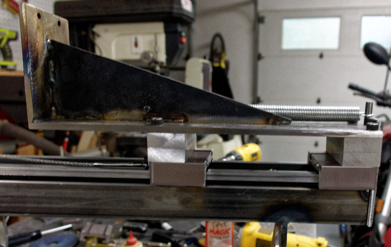
The face must be perpendicular to the base
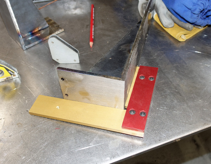
Straight and square
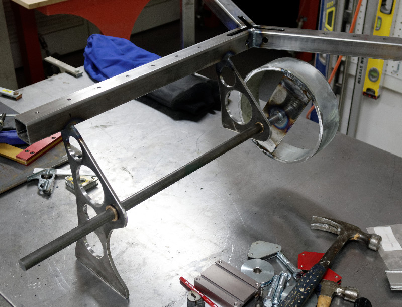
Test fit to see that everything lines up
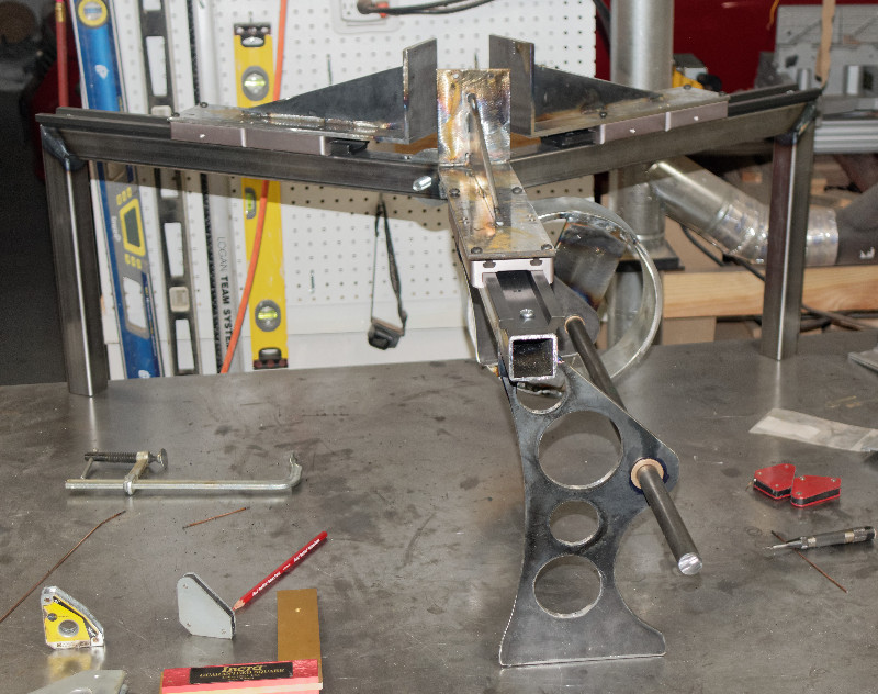
All is well
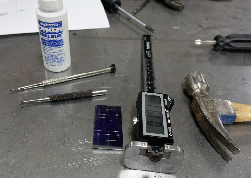
Manual layout the old school way, with Dykem, scribe and center punch. I really need a CNC mill
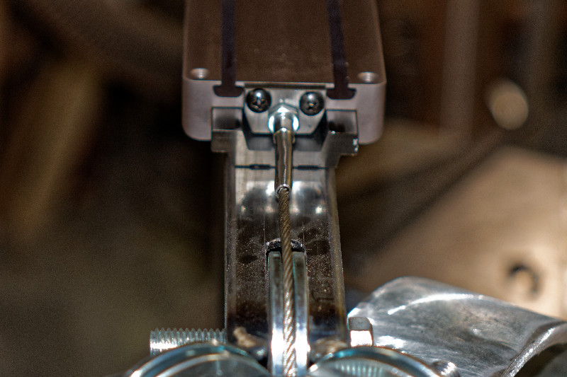
The tool for crimping the connector on the cable costs $5500. I beat on the connector with a big hammer..hope it holds
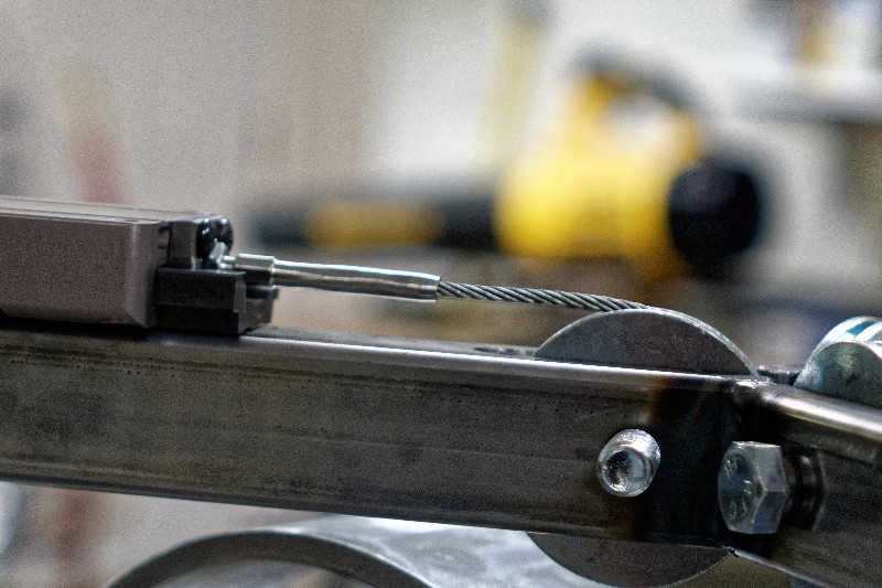
Everything lines up
All is well
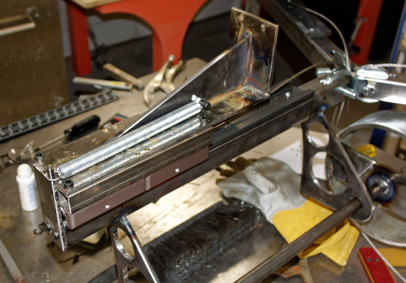
After much searching and confusion, found a good spring
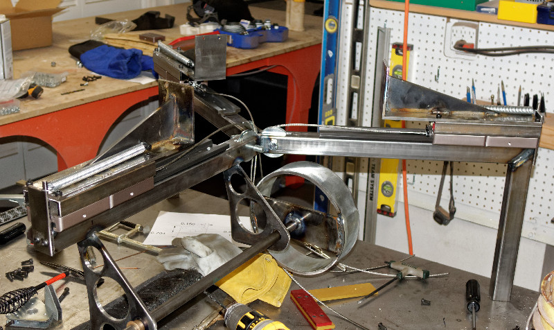
All springs mounted. Everything works with the mounting screws loose
Problem..When the mounting screws are tightened, everything binds. Try sanding flat
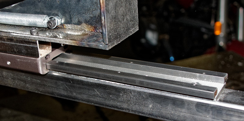
The slides are very precise, well beyond the precision of my shop. We had lots of slides in stock, and they seemed to be a good choice at the time, With 20/20 hindsight, I now realize that this was the wrong decision. The good news is, the machine doesn't need to be super precise, so grind down the rails and loosen tolerances
More trouble. The slides worked because the special coating on the rails worked well with the "Frelon Gold" bearing material (fluoropolymer with metalic particles) on the slide. When the rails were ground down, sanded and polished to a smooth shine, they galled against the bearing surfaces. Hmm..time for a new approach
The new rails will be made out of an aluminum base with steel bearing surfaces. The CNC router now has a variable speed spindle. When slowed to 4000 RPM, it can drill aluminum very nicely
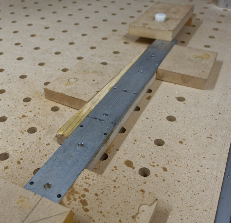
Use the aluminum parts as a drill guide, along with wood spacers to transfer holes to steel. The CNC router can't drill steel directly. Then, finish the holes on the drillpress and tap
Plan B works perfectly! Little by little, I'm getting close to machine shop precision from the CNC router, drillpress, hand tools and cleverness
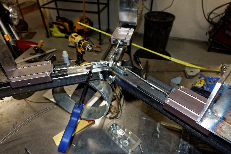
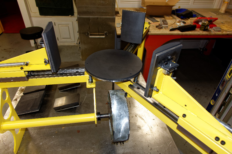
All slides, springs and cables in place
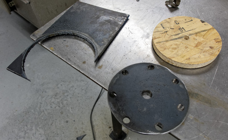
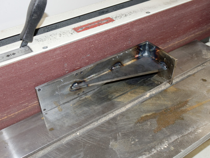
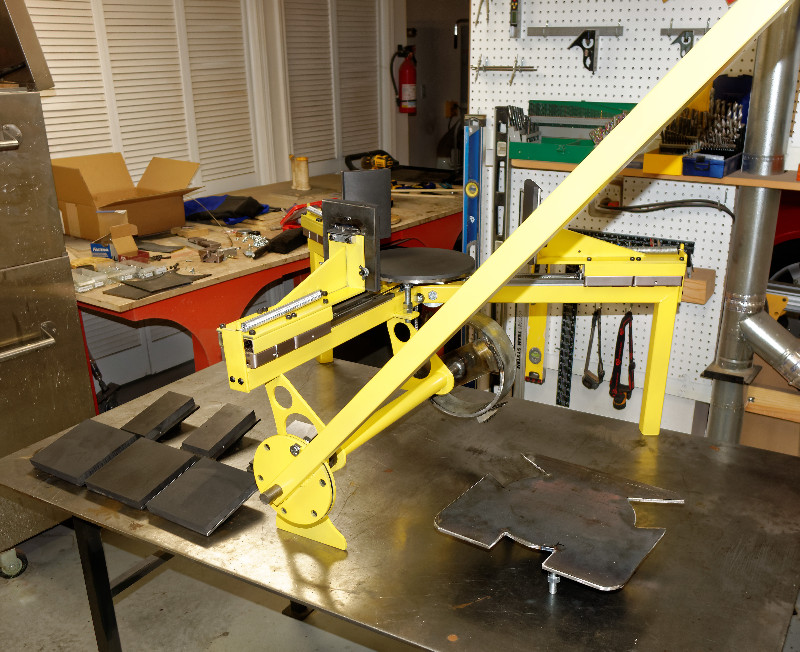
This piece is made of 1/4" steel. The holes were marked on the CNC router and drilled on the drillpress. The shape was cut with a plasma cutter, following a wood pattern that was cut on the CNC router
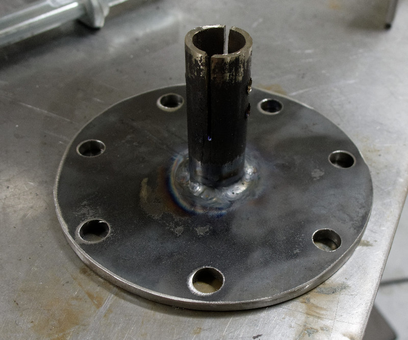
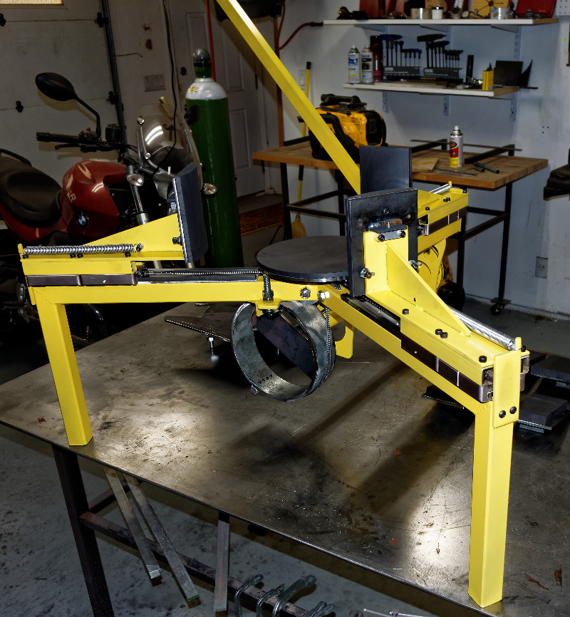
A piece of black iron pipe was slotted, drilled and welded to the plate
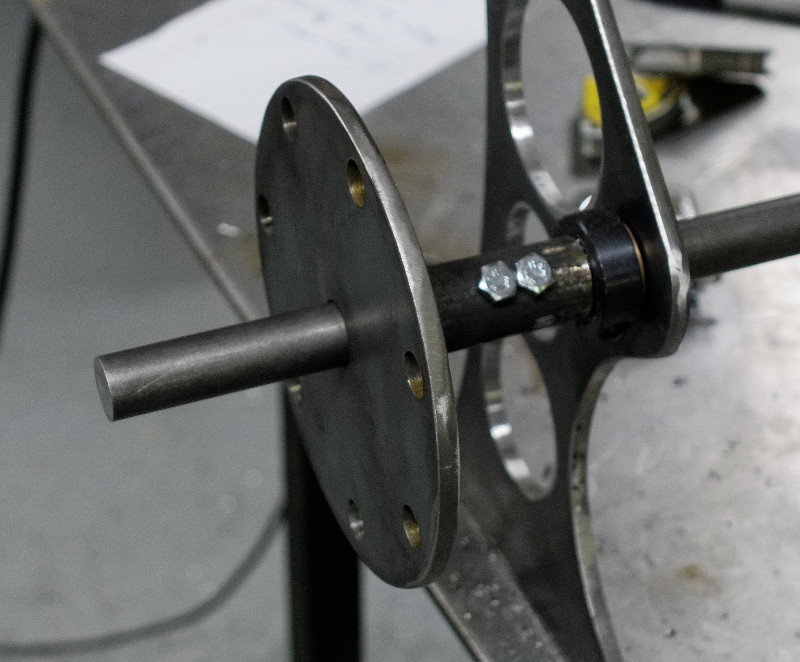
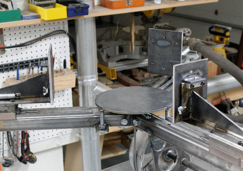
In place on the shaft. This plate has 7 holes
The mating plate has 6 holes, providing many combinations for adjustment
The center support plate is supported by three bolts. adjusted with nuts
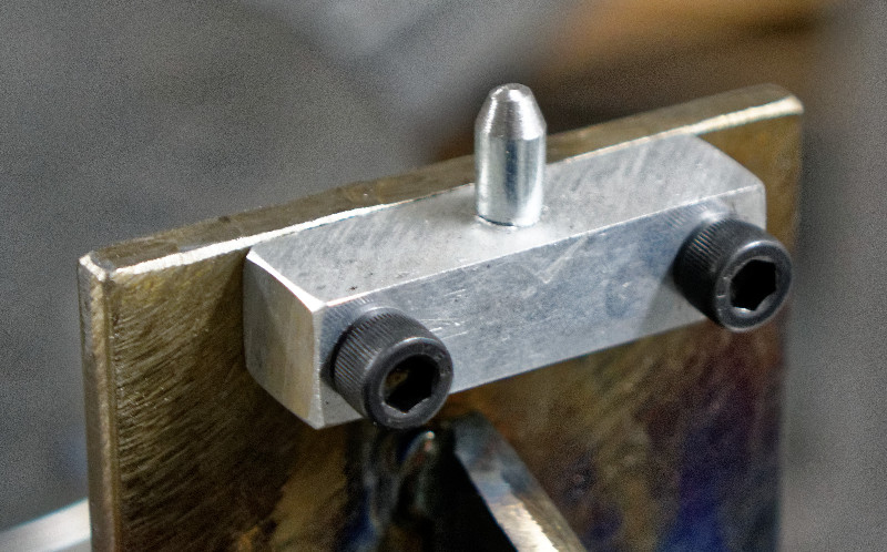
The aluminum alignment block was drilled on the CNC router. The pin was shaped on the belt sander while held in a drill chuck
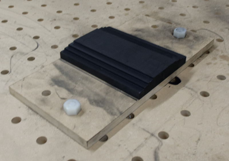
Quick disconnect graphite backing plate fits over tapered pin and can be secured with thumbscrews if needed
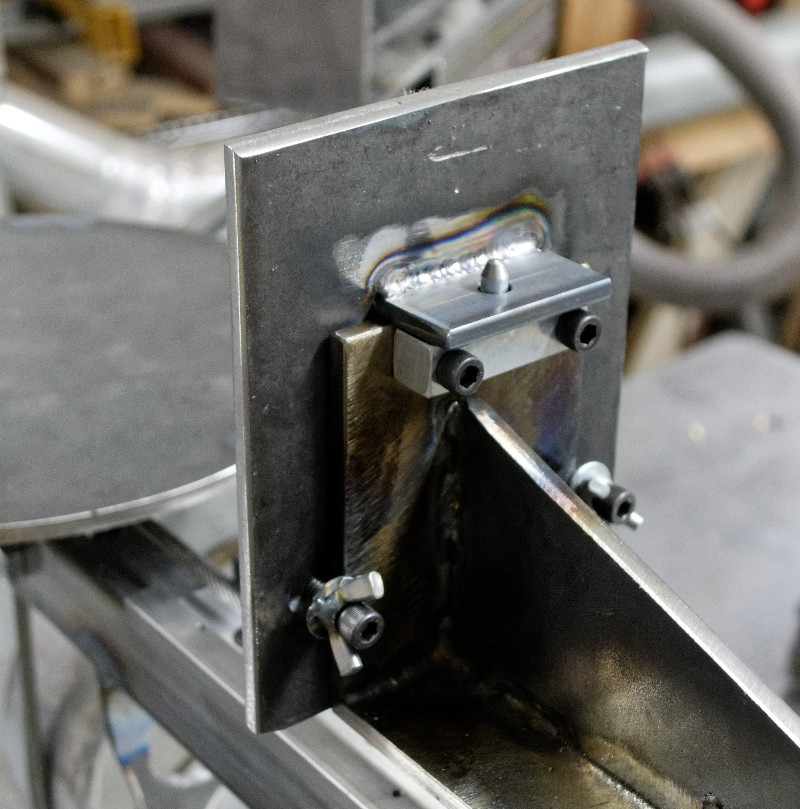
Ready for the CNC machined graphite
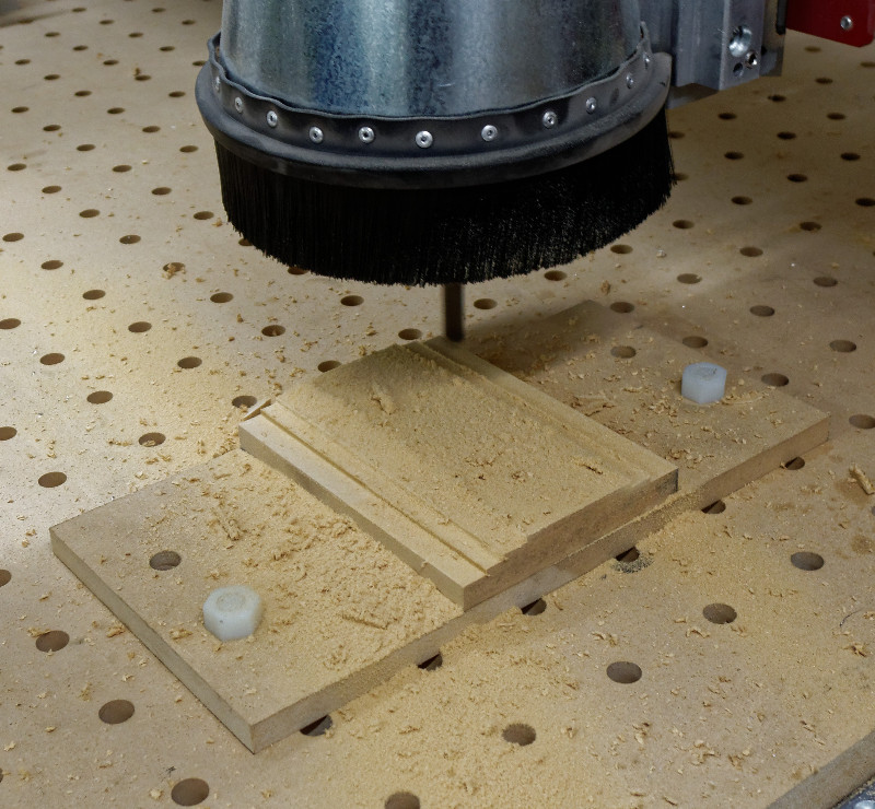
I don't have extra graphite, so check program with MDF
Graphite rough cut
First set of graphite dies complete
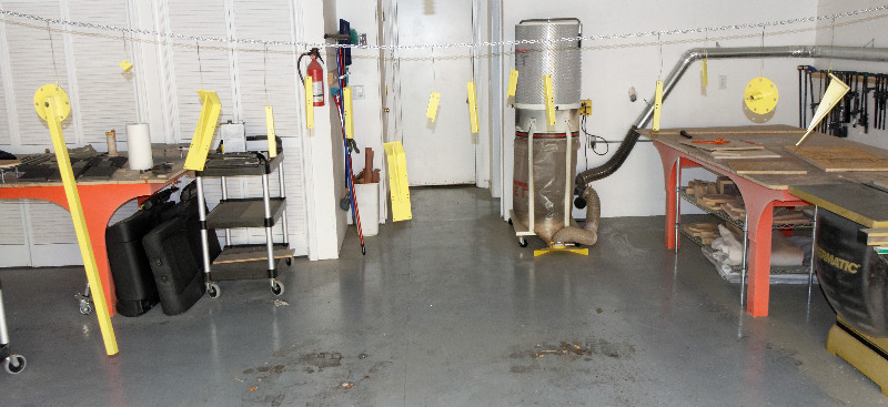
I don't have a proper spray booth, but I do have chain and soft steel wire
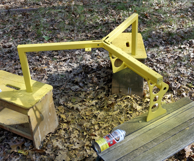
Base painted with high temperature yellow..My favorite color
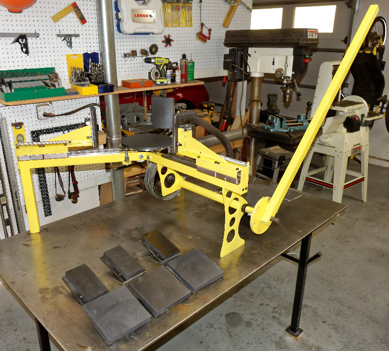
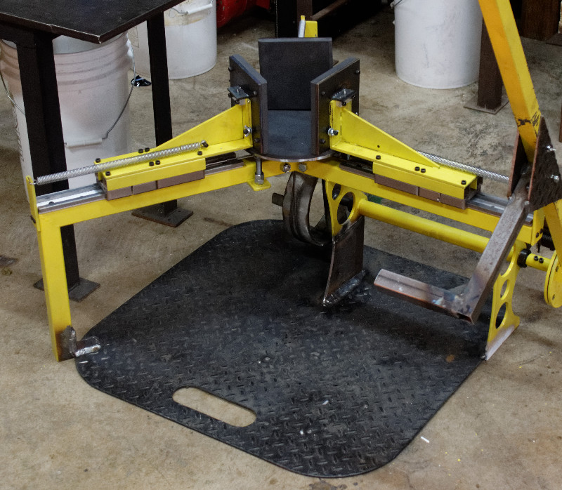
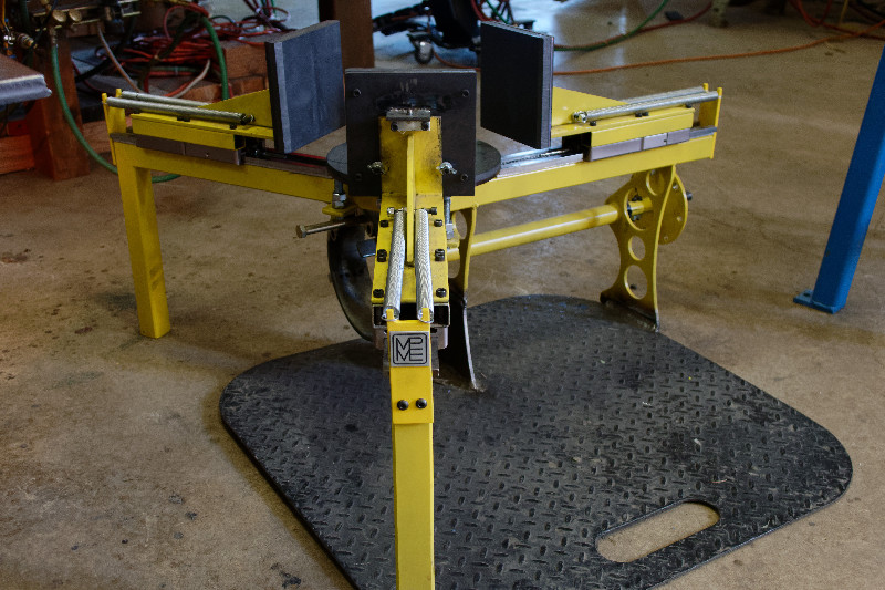
The finished project, with three sets of forming dies
A secondary support is provided for the portable electric kiln
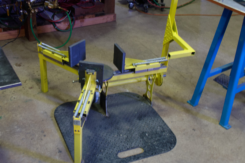
Another view
Now .. on to testing!
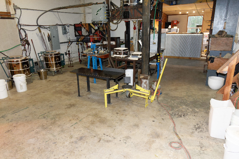
In place in Marcel's studio
After some minor tweaks and adjustments, the first test was a success!
The machine was used several times the first night, while Marcel developed his technique and came up with ideas for improvement The next day, we all reviewed operation. Although the machine worked, Marcel noticed some flexing in the frame as he pulled the handle (He pulled harder than I expected). Many ideas were discussed
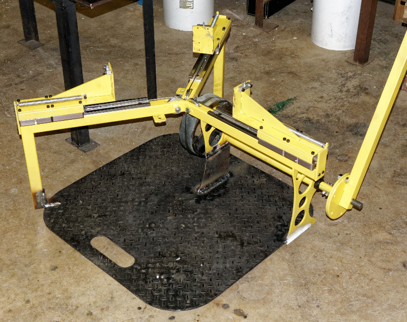
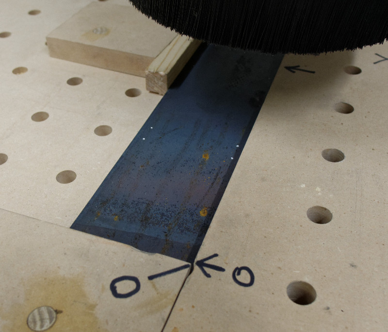
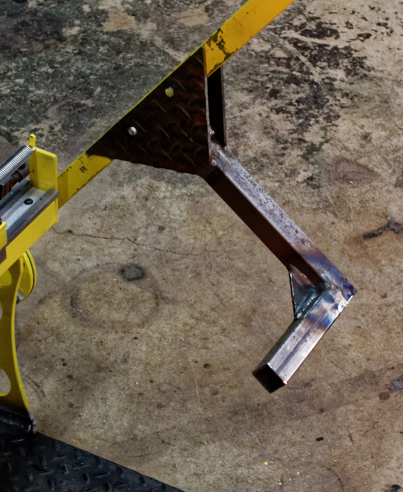
Marcel scrounged around in his junk yard and found a piece of heavy steel diamond plate that fit almost perfectly. Then, he and Samuel Isacks (Sir Pyro) went out in the shop and welded the plate in place. This dramatically increased stiffness
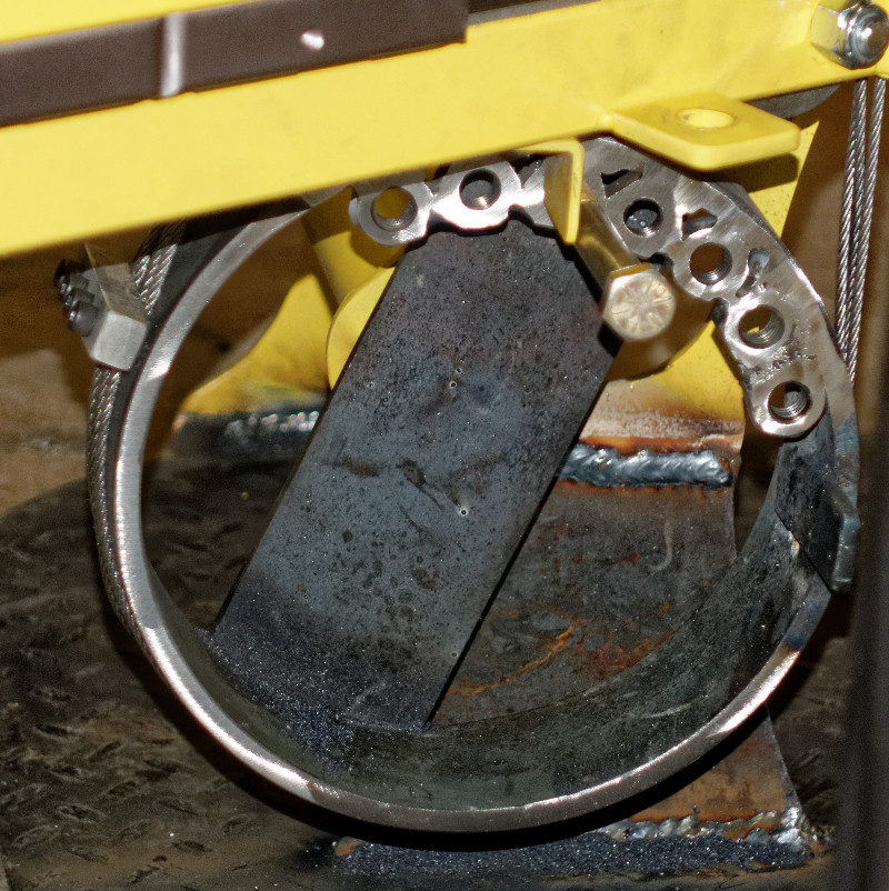
Marcel also wanted more positions on the back stop, as well as a foot pedal option added to the handle. So, he and Pyro went back in the shop to add the mods. A row of welded nuts provided an adjustable back stop
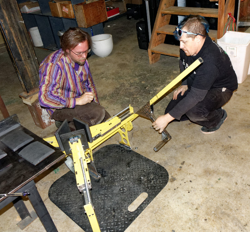
Marcel and Sir Pyro fitting the footpedal
The footpedal was bolted, not welded, to allow for adjustment
The mods worked well, and Marcel continued to use the machine many more times while I was there
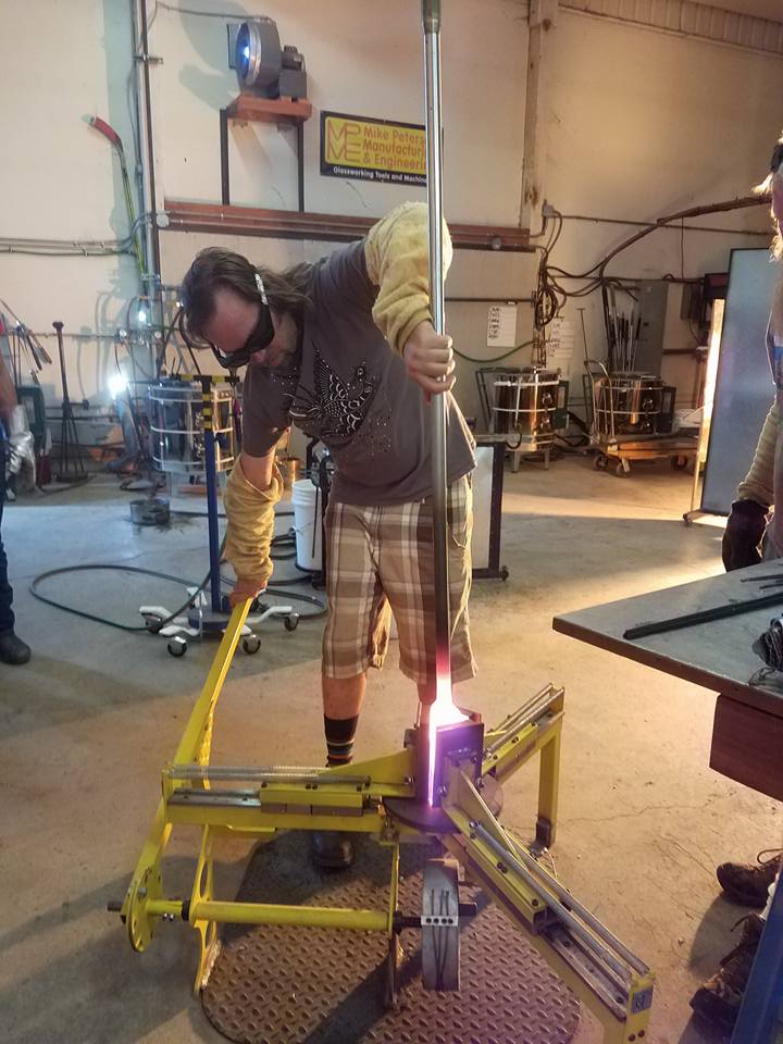
First Use
In Action
The added footpedal overpowered the single spring. So, on the next visit, add a second spring with logo
And paint the footpedal
Still going strong in August 2017